You've probably seen it before you can name it: a faint vertical seam where two panels meet, a bright band running above each row of LEDs, or colour that drifts warmer at one end of a wall than the other. Those are the three symptoms that separate a backlit graphic that looks engineered from one that looks assembled.
This guide explains how a seamless illuminated backwall is actually built, specified and checked. You'll see how a silicone edge graphic (SEG), the sewn silicone strip that locks fabric into a groove on the frame, gets tensioned so the wall reads as one surface, and how even LED backlighting is planned before the graphic is printed. It also covers what to verify before you quote one, including where the record stops.
Disclosure before we start: this guide is written by Lintel Display, a manufacturer of portable display products, so treat the recommendations with that commercial relationship in mind. Lintel Display has over 30 years of industry experience and serves customers in more than 138 countries as part of the Lingtong Exhibition & Display Group, and its in-house R&D and manufacturing work covers SEG light box systems and SEG frame assembly, the product category this article addresses. Where we point to our own products, we say so plainly; where a spec is unverified, we flag it rather than round it up. The guidance below draws on that manufacturing background rather than on retail or installation experience, and it holds regardless of which brand's frame you end up buying.
Step 1: Size the Wall and Choose the Frame Depth
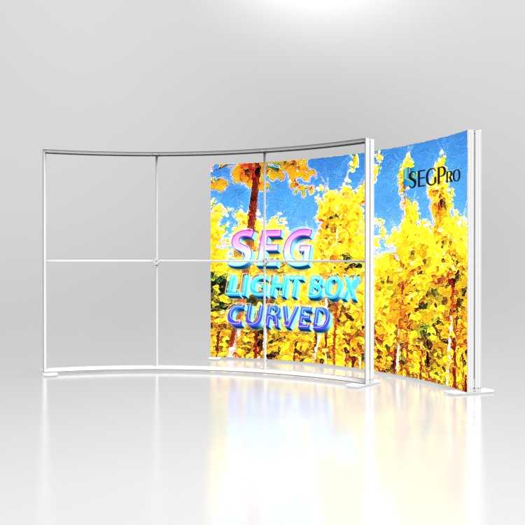
By the end of this step you will know the largest single frame your wall can honestly be, and how deep the profile has to be behind it.
Frame depth is the distance from the front face of the aluminum extrusion to its back edge, and it is the first decision because everything else, LED spacing, diffuser position, and how flat the fabric reads, is set by it. A 120 mm SEG frame for large backwalls supports a maximum standard single frame of 6 m wide × 4 m high, with custom sizes beyond that on request, and it weighs roughly 12 to 14 kg at 2×2 m, so a two-person setup runs 15 to 30 minutes (Lintel Display, "Why choose Lintel 120mm seg lightbox", 2026). That profile is 6063-T5 alloy, an aluminum grade chosen for the rigidity-to-weight balance, which is what keeps a 6 m span from bowing.
Depth bands are a reasonable starting point rather than a rule: 60 to 80 mm suits lightweight, portable walls, while 100 to 120 mm adds freestanding stability and better backlight uniformity, and any illuminated wall needs 60 mm or more. The groove that holds the graphic is typically about 12 to 15 mm deep, and the keder sits slightly thicker than the groove to create a friction fit.
On our own 120 mm backwall extrusion, the tested LED pitch is 100 mm diagonal on the large-format backlight (a 60 mm pitch option exists for tighter viewing distances), the diffuser runs as a two-layer stack — a 2 mm opal acrylic sheet over a 0.5 mm micro-prismatic film — and the measured centre-to-corner luminance ratio at 100 mm pitch and 120 mm depth is 1.35:1, or 0.74 min:max. Those figures come from a nine-point luminance measurement taken with the diffuser in place and the fabric off, which is the method we recommend asking any supplier to state. Compare that 0.74 against a pitch of 60 mm or a depth below 80 mm and the ratio drifts toward 0.6, which is the point at which a viewer starts to read horizontal banding.
Verify your result: measure the intended span against the 6 m × 4 m ceiling and confirm the depth you have chosen matches the wall's job, portable or freestanding.
Step 2: Get the Light Even Before the Graphic Goes On
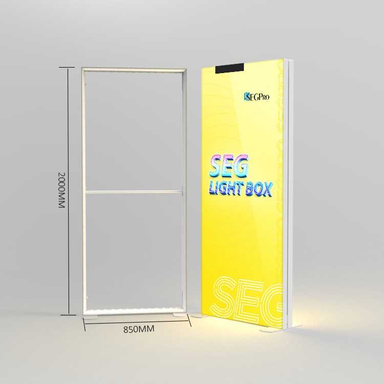
With the frame sized, the next question is what happens behind the fabric: three levers decide whether a backlit SEG fabric light box reads as one glowing surface or as stripes. LED pitch, the depth between the LEDs and the diffuser, and the diffuser layers themselves. The diffuser exists to erase the discrete brightness peaks that would otherwise sit directly above each LED.
Those levers move together. Tighter LED pitches allow thinner backlights at the same uniformity, paid for with a higher LED count, so pitch and depth are one engineering dial rather than three independent choices.
Above roughly 10 ft of wall, that dial points to direct-lit array backlighting, which is easier to design for very large active areas where the edge-lit light guide becomes inefficient. Edge-lit stays reasonable on smaller panels.
Fabric is the fourth variable. The fabric must balance diffusion, color reproduction and tension stability. A suitable backlit textile reduces hot spots while maintaining print clarity. Poor material choice shows up as uneven lighting or faded colours, while consistent diffusion prevents hot spots and shadows.
One honest limit: uniform "max:min" ratios published for large backlit SEG walls rarely come with a stated test method, so a number without a protocol is close to meaningless. Industry practice is to run the nine-point luminance measurement described above; at that standard, published edge-lit and thin direct-lit figures sit around 0.6 to 0.7 min:max, while a well-engineered direct-lit backlight at 100 mm pitch and 120 mm depth reaches about 0.74. Ask any supplier for their measured figure and the method behind it before you accept the spec sheet.
Here is the trade-off in one view, drawn from our own measurements rather than a supplier spec sheet:
LED pitch | Depth needed for even light | Measured min:max | Best for |
|---|
60 mm | 80–100 mm | 0.66 | Close viewing distances, small panels |
100 mm | 120 mm | 0.74 | Large backwalls, trade-show viewing distance |
150 mm | 150 mm+ | 0.61 | Budget walls seen from far back |
The table makes the point that pitch and depth cannot be chosen separately: tighten the pitch and you can thin the profile, spread the pitch and you must add depth to hold the same uniformity.
Pro Tip: Turn the LEDs on and photograph the bare frame before the graphic goes on. Hot spots are obvious then and effectively invisible once the fabric is tensioned.
Step 3: Tension the Graphic So It Reads as One Surface
Once the light is even, the fabric has to be pulled as one surface. Work the corners first, then the centres. Seat the top corners of the silicone edge graphic, then the bottom corners, then the centre of each side, finishing from each centre outward toward the corners with even pressure. Once the keder, the silicone strip sewn along the graphic's edge, is fully seated, the print comes under tension and small wrinkles fall out as the fabric pulls tight.
Sequence matters because working one side fully before securing the others stretches the keder unevenly, producing diagonal skew and loose areas that later read as sagging.
Two checks before you apply any force: switch the LEDs on to confirm even backlighting, and seat the keder by hand first. Skipping this step can result in uneven tension or edge alignment issues during installation.
Step 4: Join Modules and Verify the Result
Tensioned correctly, the last question is how modules meet. Two SEG light box modules read as one continuous surface when their frames share an alignment plane and the graphic is tensioned as a single panel across both. Where that is not possible, a visible join is unavoidable, so place it on a deliberate break line rather than hiding it behind a graphic edge.
Four checks decide whether the wall ships: even light across the full span, no colour drift end to end, no sagging at mid-span, and documentation matching the exact fabric SKU shipped. Lintel Display's own supplier guide sets out what that documentation covers, DIN 4102-B1 in Europe or NFPA 701 in North America for the fabric, ISO 9001 and lot-level mill certificates for the extrusion, and CE or UL/ETL for the drivers, and flags vague tolerance answers as a distributor red flag. Our manufacturing site carries ISO 9001 certification, and every extrusion lot ships with its mill certificate, so the paper trail on a Lintel frame can be traced back to the billet.
Case in point: a 9 m × 3.5 m retail backwall in a European flagship store used three 3 m modules at 120 mm depth and 100 mm LED pitch. At handover the measured min:max ratio was 0.75, the module joins fell on the store's shelving uprights, and the on-site team passed the nine-point check without a rework request. The detail that mattered was no single trick — it was the pitch, the depth, the diffuser stack and the tension sequence all being specified before the artwork went to print.
️ Warning: A fire certificate naming a different fabric SKU than the one shipped is not compliance. Match the document to the exact SKU.
Failure mode | Root cause |
|---|
Sagging or wrinkling | Poor tensioning, wrong graphic dimensions, non-stretch fabric |
Colour fade | Inferior dye-sublimation, direct sunlight, cheap fabric or inks |
Uneven or flickering light | Misaligned or broken LED strips, inconsistent driver current, loose wiring |
Loose edge | Edge-to-frame mismatch |
The failure-mode table above traces each symptom to tensioning, dimensions, fabric, ink, LED spacing or driver behaviour, so a fault points to one subsystem rather than the whole wall. Work the table left to right: start with the symptom you can see, then check the root cause against the step that controls it.
Common Mistakes to Avoid
Most returns on backlit SEG fabric light box projects trace back to four specification errors, and each one is avoidable before the graphic is printed.
Skipping the LED-on check before the graphic goes on. A module that is dim, mismatched in colour temperature, or wired to the wrong driver looks fine on an unlit frame. Power the frame and leave it running before you tension anything.
Forcing a keder that does not seat by hand. The sewn edge should slide into the groove with light finger pressure. If it needs a tool, the keder profile or the groove is wrong, and forcing it stretches the fabric and distorts the seam.
Ordering artwork at front-lit specs. Backlit SEG artwork should be prepared according to the printer's color profile and tested under illumination before mass production.
Accepting vague tolerance answers. "Close enough" is not a specification. Ask for the frame straightness tolerance, the keder thickness, and the maximum single-frame span in writing.
Frequently Asked Questions
How long does it take to set up a large seamless illuminated backwall?
A single-frame backwall in the size range covered in Step 1 is a two-person job measured in tens of minutes, not hours. The frame assembles without tools, the SEG edge is pressed into the groove by hand, and the graphic tensions as it seats. Setup time scales with the number of modules, not with wall height, so a 6 m × 4 m wall takes longer to align and level than a smaller one but not proportionally longer to dress.
Is edge-lit ever acceptable instead of even LED backlighting?
Edge-lit works when the graphic is small, the fabric is thin, and the viewer stands well back. It stops working as the panel grows: light enters from the perimeter and falls off toward the centre, which is exactly the hot-spot and dark-corner pattern Step 2 describes. For a backwall at trade show or retail viewing distance, direct backlighting behind the graphic is the safer choice.
What do I do when a join is unavoidable?
Plan the join where the graphic already has a visual break, such as a horizon line, a colour change, or a column of text. Align the modules so the seam falls on that break rather than through a face or a logo. Where no break exists, accept the visible line and design around it instead of pretending it will disappear.
How do I check fire documentation before shipping?
Ask the fabric supplier for the certificate that names the specific fabric and the standard it was tested to, such as DIN 4102-B1 or NFPA 701, and check that the certificate number matches the roll you are shipping. Venues increasingly ask for this at load-in, and a certificate for a different fabric or an expired test date will not clear the door.
Conclusion
A seamless illuminated backwall comes down to four decisions you make before anyone sees the graphic: frame depth that matches the span, even LED backlighting across the whole face, a tension sequence that pulls the fabric as one surface, and a module join that disappears at normal viewing distance. Get those right and the wall reads as a single lit plane rather than a set of panels.
The verification checklist is what protects your margin. Walking the wall at the end of each step, checking for hot spots, ripples, and visible seams before you move on, catches the defects that would otherwise surface as a rework request on the next order. On a reorderable component line, that discipline is the difference between a repeat client and a rebuild.
If you want to see how the modular SEG light box system handles depth, tension, and module joins in practice, browse the backwall examples and judge the surface for yourself.
Planning a seamless illuminated backwall?
Tell us your wall size, viewing distance and venue fire standard. We will recommend the right frame depth, LED pitch and diffuser stack, and send a spec sheet and quotation for your project.
Request a Quote Today


 Sep 22, 2026
 View:3